
Usha Martin Structural Systems
Products
Showing all 3 results


Showing all 3 results


Spiral Strands
Description
Spiral Strands are assembly of two or more layers of round wires held helically around a centre usually of a single round wire. The wires are generally laid in opposite direction at different layers which is known as contra lay arrangement.
Direction of lay
In Usha Martin Structural Systems outer layer of wires in spiral strands are of right hand lay unless mentioned by the customers.
Protection from corrosion
The wires have galvanized coated surface finish. If specially called for ; the wires can be given additional protection against corrosion in the inner payers of the strands with a compatible filling of an active pigment(inorganic zinc paint) that remains like a paste. Usha Martin Structural Systems gives dosing of the inner filling in such a manner that it does not emerge from the strands while in use.
Tensile grade
The Spiral Strands supplied by Usha Martin Structural Systems India are 1570 grade & 1770 grade. However, strands with lower grades can also be supplied.
Construction
The Strands of following construction are commonly used in Usha Martin Structural Systems.
However, tailor-made designs to suit consultants’/contractors’ requirements can also be taken up.
- 1×7 (6-1)
- 1×19 (12: 6-1)
- 1×37 (18: 12: 6-1)
- 1×61 (24: 18: 12:6-1)
- 1×91(30:24: 18: 12:6-1)
- 1×127(36:30:24: 18: 12:6-1)
Pre-stretching
Spiral Strands are pre-stretched under controlled conditions.
End Fittings
Spiral Strands are supplied with end fittings having desired lengths within the specified tolerances and is ready to install condition as per the requirements.
<!–  –>
–>
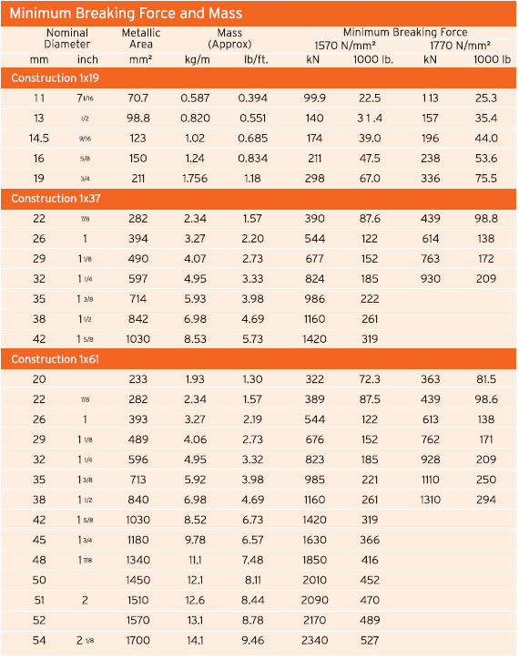
| Minimum Breaking Force and Mass | ||||||||
|---|---|---|---|---|---|---|---|---|
| Nominal Diameter | Metallic Area | Mass (Approx) | Minimum Breaking Force | |||||
| 1570 N/mm2 | 1770 N/mm2 | |||||||
| mm | inch | mm2 | kg/m | lb/ft | kN | 1000lb | kN | 1000lb |
| Construction 1×19 | ||||||||
| 11 | 71/16 | 70.0 | 0.587 | 0.394 | 99.9 | 22.5 | 113 | 25.3 |
| 13 | 1/2 | 98.8 | 0.820 | 0.551 | 140 | 31.4 | 157 | 35.4 |
| 14.5 | 9/16 | 123 | 1.02 | 0.685 | 174 | 39.0 | 196 | 44.0 |
| 16 | 5/8 | 150 | 1.24 | 0.834 | 211 | 47.5 | 238 | 53.6 |
| 19 | 3/4 | 211 | 1.756 | 1.18 | 298 | 67.0 | 336 | 75.5 |
| Construction 1×37 | ||||||||
| 22 | 7/8 | 282 | 2.34 | 1.57 | 390 | 87.6 | 439 | 98.8 |
| 26 | 1 | 394 | 3.27 | 2.20 | 544 | 122 | 614 | 138 |
| 29 | 11/8 | 490 | 4.07 | 2.73 | 677 | 152 | 763 | 172 |
| 32 | 11/4 | 597 | 4.95 | 3.33 | 824 | 185 | 930 | 209 |
| 35 | 1 3/8 | 714 | 5.93 | 3.98 | 986 | 222 | ||
| 38 | 1 1/2 | 842 | 6.98 | 4.69 | 1160 | 261 | ||
| 42 | 1 5/8 | 1030 | 8.53 | 5.73 | 1420 | 319 | ||
| Construction 1×61 | ||||||||
| 20 | 233 | 1.93 | 1.30 | 322 | 72.3 | 363 | 81.5 | |
| 22 | 7/8 | 282 | 2.34 | 1.57 | 389 | 87.5 | 439 | 98.6 |
| 26 | 1 | 393 | 3.27 | 2.19 | 544 | 122 | 613 | 138 |
| 29 | 1 1/8 | 489 | 4.06 | 2.73 | 676 | 152 | 762 | 171 |
| 32 | 1 1/4 | 596 | 4.95 | 3.32 | 823 | 185 | 928 | 209 |
| 35 | 1 3/8 | 713 | 5.92 | 3.98 | 985 | 221 | 1110 | 250 |
| 38 | 1 1/2 | 840 | 6.98 | 4.69 | 1160 | 261 | 1310 | 294 |
| 42 | 1 5/8 | 1030 | 8.52 | 6.73 | 1420 | 319 | ||
| 45 | 1 3/4 | 1180 | 9.78 | 6.57 | 1630 | 366 | ||
| 48 | 1 7/8 | 1340 | 11.1 | 7.48 | 1850 | 416 | ||
| 50 | 1450 | 12.1 | 8.11 | 2010 | 452 | |||
| 51 | 2 | 1510 | 12.6 | 8.44 | 2090 | 470 | ||
| 52 | 1570 | 13.1 | 8.78 | 2170 | 489 | |||
| 54 | 2 1/8 | 1700 | 14.1 | 9.46 | 2340 | 527 | ||
* Special requirements on breaking forces can also be met.
* Spiral Strands may be provided conforming to various relevant national and international standards to suit customer needs.
* Spiral Strands can also be provided in sizes and constructions not included in the tables of this brochure.
Locked Coil Wire Ropes
Locked Coil Wire Ropes in Usha Martin Structural Systems India are manufactured from steel throughout, being built up by laying series of concentric layers of shaped wires or a combination of round and shaped wires over a core made with round wires. The term ‘Locked Coil’ is derived from the fact that the wires of the outer layer and some of the wires of the inner layers are so designed to have a special shape so that they remain interlocked with one another. Full Locked Type construction which is more common in structural projects has an outer wire covering of ‘Z’ shaped wires which fir one to another; each wire being held in position by the adjacent wires.
Direction of lay
The wires of the outer layer in a Locked Coil Wire Rope are laid in right hand direction unless requested otherwise by the customer. The wires of the next inner layer below the top layer are
laid in opposite direction. The wires of the subsequent inner layers are laid same or opposite direction as per the requirement of design.
Protection from corrosion
Locked Coil Wire Ropes in Usha Martin Structural Systems India are manufactured from steel throughout, being built up by laying series of concentric layers of shaped wires or a combination of round and shaped wires over a core made with round wires. The term ‘Locked Coil’ is derived from the fact that the wires of the outer layer and some of the wires of the inner layers are so designed to have a special shape so that they remain interlocked with one another. Full Locked Type construction which is more common in structural projects has an outer wire covering of ‘Z’ shaped wires which fir one to another; each wire being held in position by the adjacent wires.
Tensile Grade
In order to achieve the desired breaking force of Locked Coil Wire Ropes an appropriate combination of tensile grades is used for shaped and round wires.
Construction
The arrangement of wires in the ropes is as per Usha Martin Structural Systems. A construction having multiple layers of shaped wires can be manufactured. However, Locked Coil Wire Ropes of special construction can be designed as per the requirement of the customer.
Pre-stretching
Locked Coil Wire Ropes are pre stretched under controlled conditions.
End Fittings
Locked Coil Wire Ropes are supplied with end fittings having desired lengths within the specified tolerance and in ready to install condition as per the requirements.
 –>
–>
| Minimum Breaking Force and Mass | ||||||||||
|---|---|---|---|---|---|---|---|---|---|---|
| Nominal Diameter | Metallic Area | Mass (Approx) | Minimum Breaking Force | |||||||
| 1370 N/mm2 | 1470 N/mm2 | 1570 N/mm2 | ||||||||
| mm | inch | mm2 | kg/m | lb/ft | kN | 1000lb | kN | 1000lb | kN | 1000lb |
| Center of Round Wires and 1 Layer of Shaped Wires | ||||||||||
| 20 | 254 | 2.16 | 1.45 | 321 | 72.2 | 344 | 77.3 | 368 | 82.7 | |
| 22 | 7/8 | 308 | 2.61 | 1.75 | 388 | 87.2 | 416 | 93.5 | 445 | 100 |
| 25 | 398 | 3.37 | 2.27 | 501 | 113 | 538 | 121 | 574 | 129 | |
| 26 | 1 | 430 | 3.65 | 2.45 | 542 | 122 | 582 | 131 | 601 | 140 |
| 28 | 499 | 4.23 | 2.84 | 629 | 141 | 674 | 152 | 720 | 162 | |
| 29 | 1 1/8 | 535 | 4.54 | 3.05 | 674 | 152 | 723 | 163 | 773 | 174 |
| 30 | 572 | 4.86 | 3.27 | 722 | 162 | 774 | 174 | 827 | 186 | |
| 32 | 1 1/4 | 651 | 5.53 | 3.72 | 821 | 185 | 881 | 198 | 941 | 212 |
| 34 | 735 | 6.25 | 4.20 | 927 | 208 | 994 | 224 | 1060 | 239 | |
| 35 | 1 3/8/ | 779 | 6.62 | 4.45 | 982 | 221 | 1050 | 237 | 1130 | 253 |
| 36 | 824 | 7.00 | 4.70 | 1040 | 234 | 1120 | 251 | 1190 | 268 | |
| 38 | 1 1/8 | 919 | 7.80 | 5.24 | 1160 | 260 | 1240 | 279 | 1330 | 298 |
| 40 | 1018 | 8.65 | 5.81 | 1280 | 288 | 1380 | 309 | 1470 | 330 | Center of Round Wires and 2 Layer of Shaped Wires |
| 25 | 412 | 3.50 | 2.35 | 520 | 117 | 558 | 125 | 596 | 134 | |
| 26 | 1 | 446 | 3.79 | 2.55 | 562 | 126 | 603 | 136 | 644 | 145 |
| 28 | 517 | 4.40 | 2.95 | 652 | 147 | 700 | 157 | 747 | 168 | |
| 29 | 1 1/8 | 555 | 4.72 | 3.16 | 699 | 157 | 750 | 169 | 801 | 180 |
| 32 | 1/1/4 | 676 | 5.74 | 3.85 | 851 | 191 | 914 | 205 | 976 | 219 |
| 35 | 1 3/8 | 808 | 6.87 | 4.61 | 1020 | 229 | 1090 | 246 | 1170 | 262 |
| 38 | 1 1/2 | 953 | 8.10 | 5.44 | 1200 | 270 | 1290 | 290 | 1380 | 309 |
| 40 | 1060 | 8.97 | 6.02 | 1330 | 299 | 1430 | 321 | 1520 | 343 | |
| 42 | 15/8 | 1160 | 9.89 | 6.64 | 1470 | 330 | 1570 | 354 | 1680 | 378 |
| 45 | 1 3/4 | 1340 | 11.40 | 7.63 | 1680 | 379 | 1810 | 406 | 1930 | 434 |
| 48 | 17/8 | 1520 | 12.9 | 8.68 | 1920 | 431 | 2060 | 462 | 2200 | 494 |
| 49 | 1580 | 13.5 | 9.04 | 2000 | 449 | 2140 | 482 | 2290 | 514 | |
| 50 | 1650 | 14.0 | 9.42 | 2080 | 467 | 2230 | 501 | 2380 | 536 | |
* Special requirements on breaking forces can also be met.
* Spiral Strands may be provided conforming to various relevant national and international standards to suit customer needs.
* Spiral Strands can also be provided in sizes and constructions not included in the tables of this brochure.